


HYDRAULIC ROTATING SHEAR
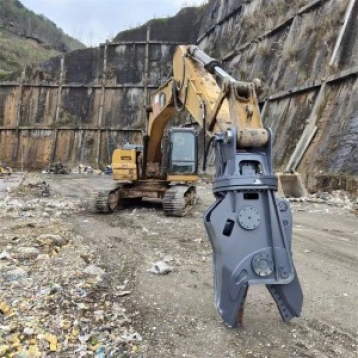
The Hydraulic Rotating Shear is a high-performance hydraulic attachment designed for excavators, specialized in precision cutting, shearing, and dismantling of rigid materials such as steel structures, scrap metal, and reinforced concrete components. Unlike fixed hydraulic shears, it integrates a 360° hydraulic rotation system, enabling flexible angle adjustment to access narrow or irregularly shaped workspaces—making it a core tool in industries like scrap metal recycling, building demolition, and end-of-life vehicle (ELV) dismantling. By leveraging the excavator’s hydraulic power, it delivers adjustable high shear force (100–800 kN) to cut through thick metal plates, steel bars, or structural beams, replacing inefficient manual cutting methods (e.g., oxy-acetylene torches) and improving both work efficiency and operational safety.1. General Definition and Core Function
The Hydraulic Rotating Shear is a high-performance hydraulic attachment designed for excavators, specialized in precision cutting, shearing, and dismantling of rigid materials such as steel structures, scrap metal, and reinforced concrete components. Unlike fixed hydraulic shears, it integrates a 360° hydraulic rotation system, enabling flexible angle adjustment to access narrow or irregularly shaped workspaces—making it a core tool in industries like scrap metal recycling, building demolition, and end-of-life vehicle (ELV) dismantling. By leveraging the excavator’s hydraulic power, it delivers adjustable high shear force (100–800 kN) to cut through thick metal plates, steel bars, or structural beams, replacing inefficient manual cutting methods (e.g., oxy-acetylene torches) and improving both work efficiency and operational safety.
2. Key Structural Components
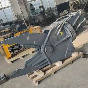
2.1 Shear Body (Frame)
Material and Durability: The main frame is constructed from high-strength quenched and tempered steel (e.g., Q960 or S960QL), with a minimum yield strength of 960 MPa and excellent impact resistance (-40℃ impact energy ≥40 J). This ensures the frame can withstand the high shear stress generated when cutting 50–100 mm thick steel plates without deformation. Critical stress points—such as the rotation joint and shear blade connection—are reinforced with wear-resistant alloy steel (e.g., HARDOX 450) plates, extending the frame’s service life to 3,000–5,000 operating hours.
Structural Design: Adopting a "double-box welded structure," the body minimizes torsional deformation during high-torque shearing. The overall weight is balanced: for mid-to-large excavators (20–40 tons), the shear weighs 2.5–5.0 tons, avoiding excessive load on the excavator’s arm. Additionally, the frame is designed with a "debris discharge slot" at the bottom—preventing metal scraps or concrete fragments from accumulating in the rotation joint and affecting 360° rotation smoothness.
2.2 Hydraulic Shear Mechanism
Dual Shear Blades: Equipped with two high-hardness shear blades (fixed blade + movable blade), made of high-speed steel (HSS) or cemented carbide (WC-Co alloy) for wear resistance and sharpness retention. The blade edge is precision-ground to a 30°–45° angle, ensuring efficient penetration into materials. For example, HSS blades can cut through Q235 steel plates up to 60 mm thick, while cemented carbide blades (used in heavy-duty models) can handle high-strength steel (Q690) up to 80 mm thick. The blades are replaceable via bolted connections—when edge wear exceeds 5 mm, they can be removed and replaced, reducing maintenance costs by 35% compared to replacing the entire shear head.
Shear Drive Cylinder: A single large-bore hydraulic cylinder (bore diameter: 120–200 mm; stroke: 300–500 mm) drives the movable blade. The cylinder barrel is made of 35CrMo alloy steel (heat-treated to HRC 28–32), and the piston rod is chrome-plated (plating thickness ≥0.08 mm) to resist corrosion and scratch. Operating at a working pressure of 30–40 MPa, the cylinder generates a shear force of 150–800 kN—for instance, a 30-ton excavator-mounted shear can produce 450 kN of force, cutting a 50 mm × 50 mm steel angle in 2–3 seconds.
2.3 360° Rotation System
Hydraulic Rotation Motor: The core component of the rotation system is a low-speed high-torque (LSHT) hydraulic motor (displacement: 500–1,500 mL/r), paired with a planetary gear reducer (reduction ratio: 50:1–100:1). The motor delivers high torque (10,000–30,000 N·m) to drive the shear head rotation, with a rotation speed of 2–5 rpm—slow enough for precise angle adjustment, fast enough to avoid delaying work cycles. The planetary gear system uses hardened steel gears (HRC 58–62) for durability, ensuring smooth rotation even under heavy loads.
Sealed Rotation Joint: The rotation joint (connecting the shear head to the frame) adopts a multi-channel sealed structure (using nitrile rubber O-rings and PTFE backup rings) to prevent hydraulic oil leakage and dust intrusion. It integrates oil passages for both the shear cylinder and rotation motor, eliminating external hose twisting during rotation. The joint is lubricated with lithium-based grease (NLGI 3) and requires only monthly grease replenishment, reducing maintenance frequency.
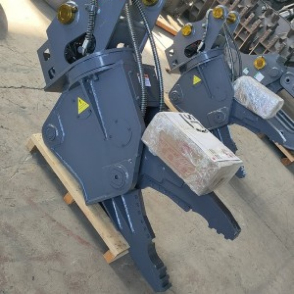
2.4 Mounting and Hydraulic Connection
Quick-Coupler Compatibility: Designed to match standard excavator quick couplers (ISO 13031 or OEM custom types), enabling tool changes in 8–12 minutes. The mounting plate is processed with CNC machining, ensuring the pin holes (diameter: 50–70 mm) have a coaxiality error ≤0.1 mm—reducing vibration during shearing and protecting the excavator’s arm.
Hydraulic Pipeline: Uses high-pressure steel wire braided hoses (DN25–DN38) with a working pressure of 45 MPa, covered with a polyurethane wear-resistant sleeve to resist gravel impact. The pipeline integrates two independent circuits: one for the shear cylinder (controlling blade movement) and one for the rotation motor (controlling shear head rotation). Quick-disconnect couplings (ISO 7241-1 A-series) with self-sealing valves are used—when disconnected, they prevent hydraulic oil leakage, avoiding environmental pollution and oil waste.
3. Working Principle
3.1 Hydraulic Power Transmission
The excavator’s hydraulic pump draws oil from the tank and pressurizes it to 30–40 MPa. The high-pressure oil is split into two circuits via a multi-way valve: one circuit supplies oil to the shear cylinder, and the other to the rotation motor. The operator controls the oil flow direction and flow rate via the excavator’s control lever—adjusting shear force (by changing pressure) and rotation speed (by changing flow) according to material type and thickness.
3.2 Shearing and Rotation Process
Angle Adjustment: The operator activates the rotation motor to rotate the shear head to the optimal angle (e.g., 45° for cutting steel beams, 90° for dismantling vehicle frames). The 360° rotation allows the shear to access materials in tight spaces (e.g., between building columns or under vehicle chassis) without repositioning the excavator.
Material Clamping: The movable blade is opened by supplying oil to the rod cavity of the shear cylinder, and the operator aligns the shear blades with the target material (ensuring the material is centered between the blades to avoid blade damage).
Shearing Operation: Oil is switched to the rodless cavity of the shear cylinder, pushing the movable blade toward the fixed blade. The high shear force generated by the cylinder penetrates and cuts the material—for example, cutting a 40 mm thick steel plate requires a pressure of 35 MPa, and the blade completes the cut in 1.5–2 seconds.
Post-Shearing Handling: After cutting, the movable blade is opened, and the rotation motor can be activated to adjust the shear angle for the next cut. The cut fragments are either dropped into a collection truck or further cut into smaller pieces (e.g., 300–500 mm lengths for scrap metal recycling).
4. Classification by Application
4.1 Scrap Metal Processing Shear
Key Features: Focus on "high-efficiency metal cutting," with sharp HSS blades, a large shear opening (400–800 mm), and a moderate shear force (150–400 kN). The rotation system is optimized for frequent angle adjustments (e.g., cutting irregular scrap metal piles). Some models add a "grapple auxiliary function"—a small grapple on the shear head to hold loose scrap metal in place during cutting.
Application Scenarios: Scrap metal recycling yards (cutting scrap steel, aluminum, or copper into manageable sizes for melting), demolition waste sorting (separating metal from concrete or wood), and industrial waste processing (cutting discarded machinery parts). For example, a scrap metal shear can process 30–50 tons of scrap steel per hour, cutting large scrap pieces into 300–500 mm lengths that fit into melting furnaces.
4.2 Building Demolition Shear
Key Features: Designed for "heavy-duty structural cutting," with cemented carbide blades, a reinforced frame, and a high shear force (400–800 kN). The shear head is equipped with a "concrete crushing tooth" on the blade edge—enabling it to cut through reinforced concrete (e.g., cutting a 200 mm thick reinforced concrete beam by first crushing the concrete and then shearing the steel bars).
Application Scenarios: Building demolition (cutting steel beams, columns, or reinforced concrete components), bridge demolition (cutting bridge piers or steel girders), and industrial plant renovation (removing large equipment foundations). A 40-ton excavator-mounted demolition shear can cut a 600 mm × 600 mm steel column into sections in 5–8 minutes, significantly faster than traditional mechanical breakers.
4.3 ELV Dismantling Shear
Key Features: Focus on "precision vehicle component cutting," with a narrow shear head (width: 200–300 mm) to access tight spaces (e.g., between vehicle body panels), and a variable shear force (100–300 kN) to avoid damaging reusable parts. The blades are rounded at the tips to prevent puncturing fuel tanks or hydraulic lines.
Application Scenarios: End-of-life vehicle dismantling (cutting vehicle frames, engine mounts, or suspension components), automotive salvage yards (removing damaged parts from wrecked vehicles), and scrap car processing (cutting car bodies into small pieces for material separation). For example, an ELV shear can dismantle a mid-sized car in 20–30 minutes, separating steel, aluminum, and plastic components with a material recovery rate of over 90%.
5. Practical Applications and Advantages
5.1 Scrap Metal Recycling: Efficiency and Cost Savings
High Processing Capacity: Compared to manual cutting (5–10 tons/hour) or oxy-acetylene torches (15–25 tons/hour), hydraulic rotating shears process 30–80 tons of scrap metal per hour—shortening the processing cycle by 60–70%. For a scrap yard handling 100 tons of scrap daily, using a shear reduces the required working time from 8 hours to 3–4 hours.
Low Operating Costs: Oxy-acetylene torches require fuel (acetylene and oxygen) costing
200 per hour, while hydraulic rotating shears only consume hydraulic oil (costing 20-30 per hour) and have lower maintenance costs (blade replacement every 1,000 hours vs. torch tip replacement every 10 hours). This reduces annual operating costs by 50,000-100,000 for a medium-sized scrap yard.
5.2 Building Demolition: Safety and Precision
Reduced Safety Risks: Operators control the shear from the excavator cab (5–15 meters away from the demolition area), avoiding exposure to falling debris, dust, or toxic fumes. The 360° rotation allows cutting without positioning the excavator close to unstable structures—reducing the risk of structural collapse accidents by 80% compared to manual demolition.
Precision Demolition: The adjustable shear force and rotation angle enable precise cutting of specific components (e.g., cutting a single steel beam without damaging adjacent structures). This is critical for "selective demolition" (e.g., renovating a historic building by removing only non-heritage components) or demolition in urban areas (avoiding damage to nearby buildings).
5.3 ELV Dismantling: Resource Recovery and Compliance
High Material Recovery Rate: The precision cutting of ELV shears separates different materials (steel, aluminum, copper, and plastic) with minimal contamination—for example, the recovery rate of copper wires from vehicle harnesses is over 95%, compared to 70–80% with manual dismantling. This increases the value of recycled materials by 10–15%.
Regulatory Compliance: Many countries (e.g., EU, China) have strict regulations for ELV dismantling (e.g., mandatory separation of hazardous materials like lead or asbestos). Hydraulic rotating shears enable safe removal of hazardous components (e.g., cutting around fuel tanks without puncturing them) and ensure compliance with environmental standards, avoiding fines of
50,000 for non-compliance.
6. Operational and Maintenance Considerations
6.1 Excavator Matching Requirements
Weight Compatibility: The shear’s weight should not exceed 20–25% of the excavator’s operating weight (e.g., a 20-ton excavator should use a shear weighing ≤5 tons). Excessive weight will cause the excavator’s arm to sag, increasing fuel consumption by 15–20% and accelerating arm hinge wear.
Hydraulic System Matching: The excavator’s hydraulic flow should be 40–100 L/min (matching the shear’s flow requirement). If the flow is too low, the shear blade movement and rotation speed will slow down (reducing efficiency by 30–40%); if too high, the hydraulic motor and cylinder will overheat (shortening their service life by 50%).
6.2 Routine Maintenance
Blade Maintenance: Inspect the shear blades daily—grind the blade edge when wear exceeds 3 mm (using a diamond grinding wheel to maintain the 30°–45° angle). Replace blades when the edge is chipped or worn beyond 5 mm to avoid increasing shear force requirements (which can damage the hydraulic cylinder).
Rotation System Lubrication: Grease the rotation joint and planetary gear reducer every 8 hours of operation (using lithium-based grease NLGI 3). Check the grease level in the rotation motor weekly—add grease if the level is below the minimum mark to prevent gear wear.
Hydraulic System Inspection: Check the hydraulic hoses and couplings for leaks or cracks weekly—replace damaged hoses immediately (using hoses of the same pressure rating to avoid bursts). Change the hydraulic oil and oil filter every 1,500 operating hours (using oil that meets ISO VG 46 standards) to prevent oil contamination from clogging the rotation motor or cylinder.
6.3 Safety Operation Rules
Operator Training: Operators must complete specialized training to master shear operation—including understanding shear force limits (e.g., not cutting materials thicker than the blade’s rated capacity), rotation speed control, and emergency stop procedures. They should also be familiar with material properties (e.g., high-strength steel requires higher pressure than ordinary steel).
On-Site Safety: Before operation, clear the site of personnel and obstacles (e.g., overhead power lines) to prevent fragments from injuring people or damaging equipment. When cutting large structures (e.g., steel columns), use a rope to secure the structure to avoid sudden falling after cutting. Do not rotate the shear head when the blades are under load (e.g., mid-cut) to prevent damage to the rotation joint.