


Excavator Railway Sleeper Mchine
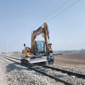
The Excavator Railway Sleeper Machine is a specialized hydraulic attachment system modified from standard excavators, dedicated to railway sleeper (tie) maintenance tasks—including sleeper replacement, ballast cleaning, and track alignment adjustment. Unlike general construction excavators, it integrates railway-specific components (e.g., rail-guided wheels, sleeper grippers) and precision control systems, enabling safe and efficient operation on active or inactive railway tracks. This equipment is a core tool in railway engineering, replacing labor-intensive manual sleeper work (which requires 4–6 workers per task) and reducing operation time by 50–70%. It is compatible with both wooden and concrete sleepers, adapting to standard railway gauges (1435 mm for international standard, 1520 mm for broad gauge) and working in complex environments such as tunnels, bridges, and high-altitude sections.1. General Definition and Core Function
The Excavator Railway Sleeper Machine is a specialized hydraulic attachment system modified from standard excavators, dedicated to railway sleeper (tie) maintenance tasks—including sleeper replacement, ballast cleaning, and track alignment adjustment. Unlike general construction excavators, it integrates railway-specific components (e.g., rail-guided wheels, sleeper grippers) and precision control systems, enabling safe and efficient operation on active or inactive railway tracks. This equipment is a core tool in railway engineering, replacing labor-intensive manual sleeper work (which requires 4–6 workers per task) and reducing operation time by 50–70%. It is compatible with both wooden and concrete sleepers, adapting to standard railway gauges (1435 mm for international standard, 1520 mm for broad gauge) and working in complex environments such as tunnels, bridges, and high-altitude sections.
2. Key Structural Components
2.1 Railway Adaptation System
Track-Guided Wheel Set: Equipped with 4–6 rail-guided wheels (diameter: 200–300 mm) made of high-strength cast steel (QT600-3) with a hardness of HB 200–230. The wheels are adjustable in width (1400–1600 mm) to match different gauges, and their treads are shaped to fit rail heads—ensuring the machine moves stably along tracks without derailing. The wheel set is connected to the excavator’s undercarriage via a shock-absorbing bracket (using rubber cushions) to reduce vibration during operation, protecting the track structure.
Rail Protection Pads: Installed on the wheel brackets and contact points with rails, made of wear-resistant polyurethane (Shore hardness 85–90A). These pads prevent scratches on rail surfaces and reduce noise (by 15–20 dB) during movement, suitable for operation near residential areas or in tunnels.
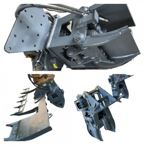
2.2 Sleeper Gripping Mechanism
Hydraulic Gripper: The core component for sleeper handling, consisting of 2–4 curved clamping arms made of high-strength alloy steel (40CrNiMoA) with a surface hardness of HRC 42–48. The inner side of the gripper is covered with rubber anti-slip pads (thickness: 10–15 mm) to avoid damaging sleeper surfaces (especially critical for concrete sleepers) and increase friction—preventing slippage when lifting sleepers weighing up to 300 kg (concrete) or 80 kg (wooden).
Gripper Drive System: Powered by 2 parallel hydraulic cylinders (bore diameter: 60–100 mm; stroke: 150–250 mm) operating at a working pressure of 20–28 MPa. The cylinders are equipped with pressure sensors to automatically adjust clamping force—applying 5–8 kN for wooden sleepers and 10–15 kN for concrete sleepers, avoiding over-clamping damage. The gripper can rotate ±30° horizontally and ±15° vertically via a hydraulic tilt cylinder, enabling alignment with sleepers in offset or tilted track sections.
2.3 Ballast Handling Attachment
Ballast Rake: Mounted on the excavator’s arm (in addition to the sleeper gripper), used to loosen and level ballast around sleepers. The rake is made of AR400 wear-resistant steel with 10–15 mm thick tines (spacing: 50–80 mm) to filter ballast (retaining particles ≥20 mm) and remove debris (e.g., stones, branches). For ballast cleaning, a optional "ballast screen bucket" (mesh size: 20×20 mm) can be installed to separate fine soil from ballast, improving track stability.
Ballast Tamper (Optional): A hydraulic tamping attachment for compacting ballast after sleeper replacement. It uses 4–6 tamping feet (made of AR500 steel) that vibrate at 30–50 Hz via a hydraulic motor, compacting ballast under the sleeper to a density of ≥1.7 g/cm³—meeting railway track stability standards (e.g., China Railway TB/T 3540-2020).
2.4 Precision Control System
Positioning Sensors: Equipped with laser positioning sensors (accuracy: ±2 mm) and GPS track mapping modules to align the sleeper gripper with existing sleepers. The system displays the sleeper’s position (lateral offset, height) on the operator’s dashboard, ensuring replacement sleepers are installed within ±3 mm of the original position—critical for maintaining track gauge and level.
Hydraulic Fine Control: The excavator’s hydraulic system is upgraded with proportional valves to adjust the gripper’s lifting speed (50–100 mm/s) and rotation angle in 0.5° increments. This allows for delicate operations, such as inserting sleepers into narrow gaps between rails (clearance: 150–200 mm) without colliding with rail fasteners (e.g., bolts, clips).
3. Working Principle
3.1 Track Movement and Positioning
The machine moves along railway tracks via the guided wheel set, with the operator using the dashboard to adjust wheel width for gauge matching. Before operation, the laser positioning system calibrates the machine’s position relative to the track centerline, and the shock-absorbing bracket reduces vibration caused by track irregularities (e.g., uneven ballast).
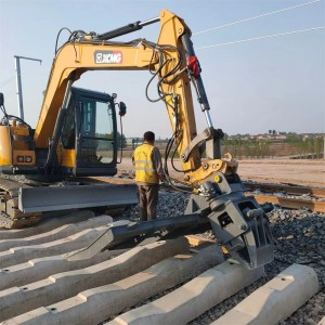
3.2 Sleeper Replacement Process
Ballast Loosening: The ballast rake is used to loosen ballast around the target sleeper (removing 100–150 mm of ballast from the sleeper’s sides and bottom) to free the sleeper from ballast constraints. For concrete sleepers, the rake avoids damaging the sleeper’s precast concrete structure.
Old Sleeper Removal: The hydraulic gripper clamps the old sleeper (centered to avoid tilting) and lifts it vertically by 50–100 mm. The gripper rotates horizontally to align with the track side, and the excavator’s arm moves the sleeper to a storage area (e.g., a rail-mounted truck) 2–3 meters away from the track.
New Sleeper Installation: The gripper picks up a new sleeper from the storage area, rotates it to match the track direction, and lowers it into the sleeper bed. The laser positioning system adjusts the sleeper’s lateral offset (≤±3 mm) and height (to match adjacent sleepers), ensuring proper rail support.
Ballast Compacting: The ballast rake or tamper refills ballast around the new sleeper, and the tamper (if equipped) compacts the ballast to the required density. This step restores track stability, preventing sleeper movement under train loads.
3.3 Ballast Cleaning (Optional)
The ballast screen bucket scoops ballast from the track, filters out fine soil and debris (≤20 mm), and returns clean ballast to the sleeper bed. This process improves ballast drainage (reducing waterlogging) and increases track bearing capacity—critical for high-speed railway sections (e.g., 200–350 km/h lines).
4. Classification by Application
4.1 Light-Duty Railway Sleeper Machine
Key Features: Modified from 6–12 ton mini-excavators, with a maximum sleeper lifting capacity of 150 kg (suitable for wooden or small concrete sleepers). The guided wheel set is lightweight (500–800 kg), and the machine has a narrow width (≤2.5 meters) to fit narrow track sections (e.g., mountain railways with limited clearance). Equipped with a basic laser positioning system (accuracy: ±5 mm) and no tamper attachment.
Application Scenarios: Rural railways, branch lines, or heritage railways with low train frequencies. Used for replacing wooden sleepers or small concrete sleepers, and light ballast cleaning. A light-duty machine can replace 8–12 sleepers per hour.
4.2 Medium-Duty Railway Sleeper Machine
Key Features: Modified from 12–20 ton excavators, with a sleeper lifting capacity of 300 kg (suitable for standard concrete sleepers). The guided wheel set has shock absorbers and a gauge adjustment range of 1400–1550 mm. Equipped with a high-precision laser positioning system (accuracy: ±2 mm) and an optional ballast rake.
Application Scenarios: Main-line railways (train speed: 120–200 km/h) and urban rail transit (e.g., metro lines during nighttime maintenance). Used for large-scale concrete sleeper replacement and ballast leveling. A medium-duty machine can replace 15–20 sleepers per hour.
4.3 Heavy-Duty Railway Sleeper Machine
Key Features: Modified from 20–30 ton excavators, with a sleeper lifting capacity of 500 kg (suitable for heavy concrete sleepers or switch sleepers). The guided wheel set uses heavy-duty cast steel wheels (diameter: 300 mm) and a reinforced undercarriage to withstand high loads. Equipped with a GPS track mapping system, hydraulic tamper, and ballast screen bucket—meeting high-speed railway standards (200–350 km/h).
Application Scenarios: High-speed railways, intercity railways, and railway switch sections (where sleepers are more complex). Used for replacing heavy switch sleepers and high-precision ballast compaction. A heavy-duty machine can replace 20–25 sleepers per hour and compact ballast to ≥1.8 g/cm³.
5. Practical Applications and Advantages
5.1 Efficiency Improvement in Railway Maintenance
Time Savings: Manual sleeper replacement takes 30–45 minutes per sleeper (with 4–6 workers), while the machine completes 15–25 sleepers per hour—reducing operation time by 60–70%. For a 10 km railway section requiring 500 sleeper replacements, manual work takes 5–7 days, while the machine finishes in 1–2 days.
Labor Reduction: A single machine (operated by 1–2 workers) replaces a team of 4–6 manual workers, reducing labor costs by 70–80%. This is particularly valuable for remote railway sections (e.g., high-altitude areas) where labor recruitment is difficult.
5.2 Precision and Safety Enhancement
Track Stability: The laser positioning and GPS systems ensure sleeper installation accuracy (±2 mm), maintaining track gauge and level—critical for high-speed railways (where track irregularities can cause train vibrations or derailment risks). The tamper attachment improves ballast density, increasing track bearing capacity by 15–20%.
Operational Safety: The machine operates from the track side, avoiding worker exposure to live tracks (reducing the risk of train collisions). The rail protection pads and shock-absorbing brackets prevent damage to existing track components (e.g., rails, fasteners), reducing maintenance costs for track repairs.
5.3 Environmental and Cost Benefits
Reduced Ballast Waste: The ballast screen bucket recycles 80–90% of clean ballast, reducing the need for new ballast procurement (saving $50–100 per cubic meter of ballast). This is environmentally friendly and lowers material transportation costs (especially for remote sections).
Minimized Track Downtime: The machine’s high efficiency reduces the time tracks are out of service—critical for busy main-line railways (e.g., 10,000+ train passages per day). Nighttime maintenance (8–10 hours) can replace 150–250 sleepers, ensuring tracks are operational for morning peak trains.
6. Operational and Maintenance Considerations
6.1 Railway Compatibility Requirements
Gauge Matching: The guided wheel set must be adjusted to match the railway’s gauge (e.g., 1435 mm for standard gauge) before operation—incorrect gauge can cause derailment. For multi-gauge railways, use a wheel set with quick-adjustment mechanisms (gauge change time ≤30 minutes).
Track Load Capacity: The machine’s weight (8–30 tons) must not exceed the track’s maximum load capacity (e.g., 20 tons for branch lines). For lightweight tracks (e.g., heritage railways), use light-duty machines (≤12 tons) and distribute weight with additional support pads.
6.2 Routine Maintenance
Guided Wheel Set Maintenance: Inspect wheel treads for wear daily—replace wheels when tread wear exceeds 5 mm (to avoid rail damage). Lubricate wheel bearings every 10 operating hours (using lithium-based grease NLGI 2) to reduce friction.
Gripper and Hydraulic System: Check the gripper’s rubber pads for wear (replace when thickness ≤5 mm) to prevent sleeper damage. Inspect hydraulic hoses (rated for 30 MPa) for leaks weekly—replace damaged hoses immediately to avoid pressure loss during sleeper lifting.
Sensor Calibration: Calibrate the laser positioning system every 50 operating hours (using a railway track calibration tool) to maintain accuracy. Clean GPS antennas daily (especially in dusty or rainy environments) to ensure signal stability.
6.3 Safety Operation Rules
Operator Training: Operators must hold railway engineering certifications and master track movement, sleeper positioning, and emergency stop procedures. Training includes simulating derailment scenarios (e.g., activating the emergency brake if the machine tilts) and understanding railway signal systems (to avoid conflicting with train schedules).
On-Site Safety: Before operation, coordinate with railway dispatch to confirm track closure times (e.g., nighttime 00:00–06:00) and set up warning signs (e.g., red flags, flashing lights) 500–1000 meters from the work area. Use a spotter (1 worker) to monitor train approaching and communicate with the operator via radio. Never operate on active tracks without dispatch approval—this can lead to catastrophic train collisions.


